Pin Relay Wiring Diagram
Pin Relay Wiring Diagram. The low-voltage side has a set of four pins and a set of three pins. Wiring Two Channel Relay Module with In the above wiring diagram we have kept the jumper in place, due to which the electromagnet of the relay will be driven directly from the Arduino.

A wide variety of relay wiring diagram options are available to you.
Relay Circuit Diagram and Working: In this Arduino Relay Control Circuit we have used Arduino to control.

12V Motorcycle Wiring Diagram With Ipnts - Collection ...

4 pin horn relay wiring - Google Search (With images ...
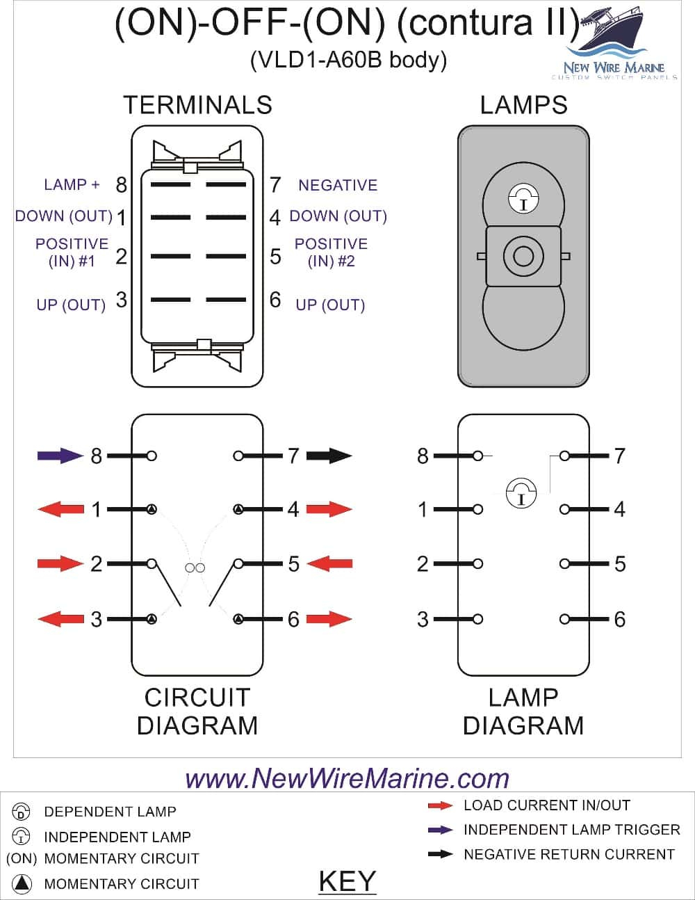
5 Pin Relay Wiring Diagram | Wiring Diagram

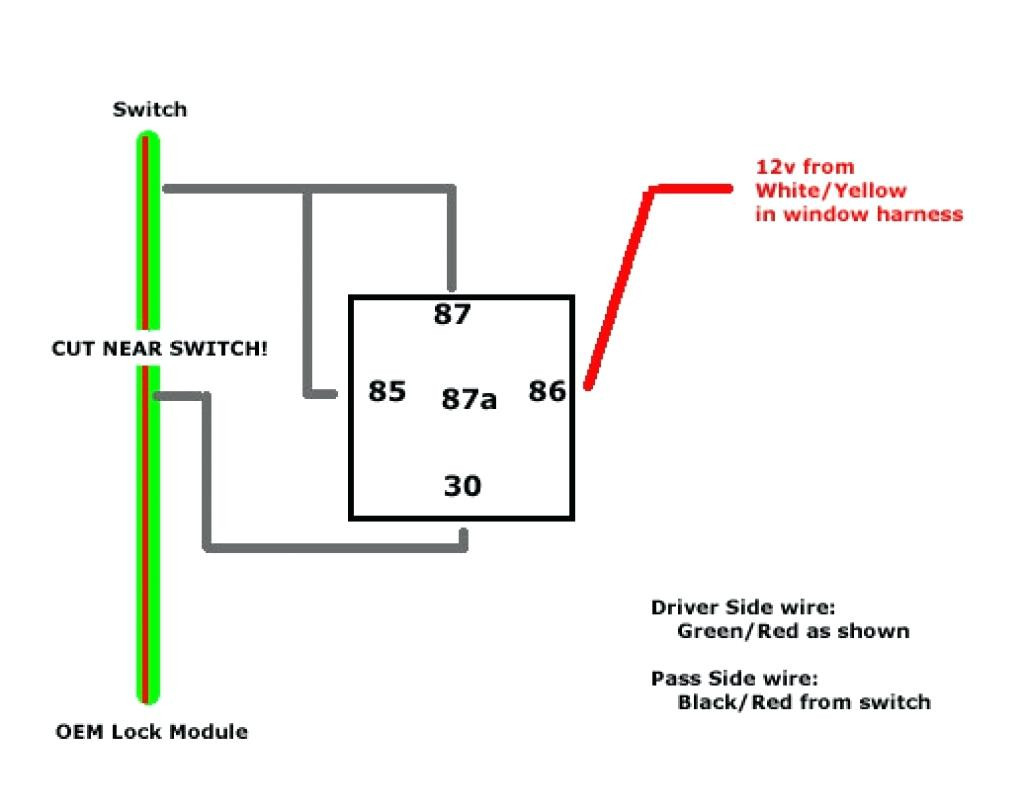
Dayton Time Delay Relay Wiring Diagram Gallery

Dayton 8 pin square ice cube relay wiring

Bosch 4 Pin Relay Wiring Diagram - Wiring Diagram And ...
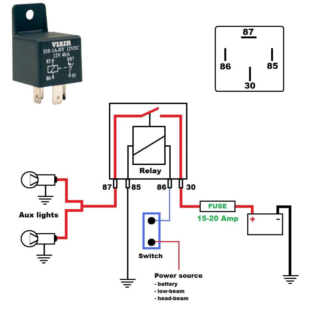
Noministnow: Bosch 5 Pin Relay Wiring Diagram
Relay Wiring Diagram 5 Pin | Wiring Diagram
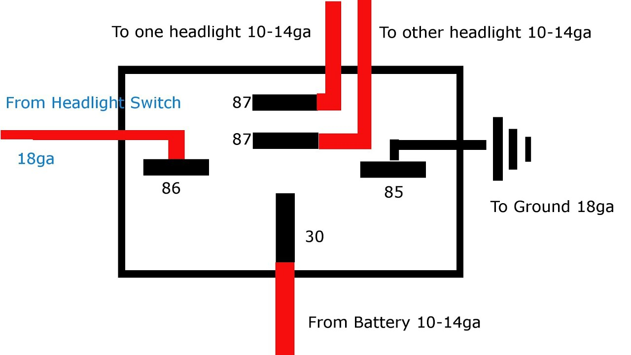
How A 5 Pin Relay Works - Youtube - 5 Pin Relay Wiring ...
Here is a video on how you can test a Relay with or without a diagram. I attached the wiring, the only difference is that I used thermistor pins instead of endstop. Control the relay by programming the pin to LOW or HIGH.

0 Response to "Pin Relay Wiring Diagram"
Post a Comment