Hp Motor Starter Typical Wiring Diagram
Hp Motor Starter Typical Wiring Diagram. Find Motor Starter Wiring Diagram related suppliers, manufacturers, products and specifications Mixer Type: Propeller / Impeller. A typical starter solenoid has one small connector for the starter control wire (the white connector in the photo) and two large terminals: one for the positive battery cable and the other.

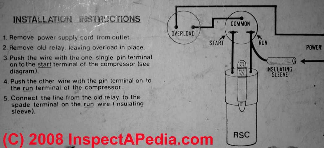
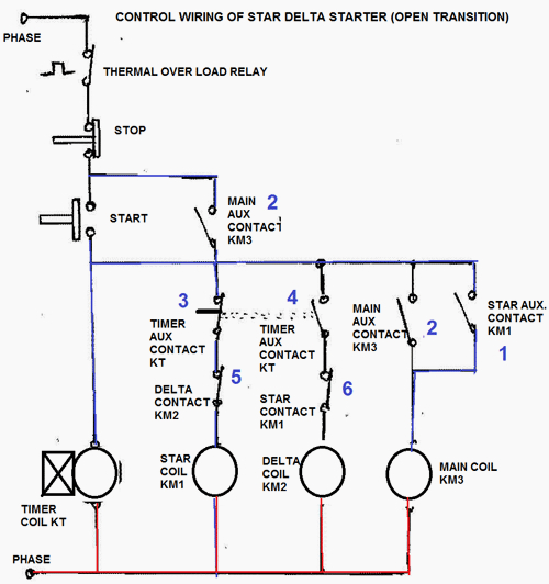
This is an example of electrical wiring diagram for a typical motor starter.
Before troubleshooting or repair work, check the earth wire is connected to the earth terminals of the main unit, otherwise an electric shock is caused when a leak occurs.
NOTE: Examples below show full load currents that may not be typical. What does the name plate on the old motor say? The starter motor can be easily bench-tested.


0 Response to "Hp Motor Starter Typical Wiring Diagram"
Post a Comment