Pin Rj Connector Wiring Diagram
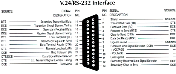
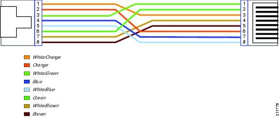
Pin Rj Connector Wiring Diagram. Below are listed the Hikvision wiring diagram from. A pinout is a specific arrangement of wires that dictate how the connector is terminated.

Below are listed the Hikvision wiring diagram from.
PoE integrates data and power on the same wires, while keeping the structured cabling safe and not interfering with Power is supplied in common mode over two or more of the differential pairs of wires found in the Ethernet.
A pinout is a specific arrangement of wires that dictate how the connector is terminated. The jack should have a wiring diagram or designated pin numbers/colors to match up to the color code below. This will attach to the computers network adapter.


0 Response to "Pin Rj Connector Wiring Diagram"
Post a Comment