Volt Regulator Lm 37 T Circuit Diagram
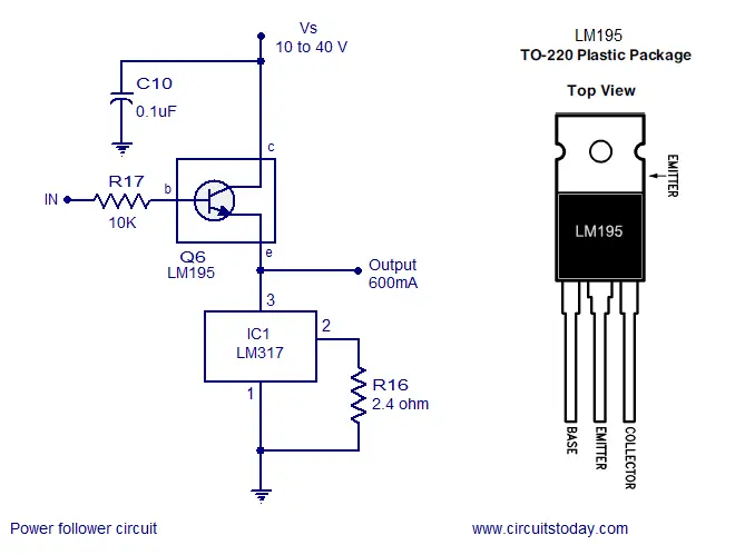
Volt Regulator Lm 37 T Circuit Diagram. This voltage regulator is exceptionally easy to use and requires only two external resistors to set the output voltage. Note: Co is not needed for stability, however, it does improve.

If the rotor further rotates, then the direction of the induced emf becomes negative.
Simple tube quenching method schematic circuit diagram.
LM317T voltage regulator project

Variable Regulated Power Supply IC LM317 - theoryCIRCUIT ...

8: Voltage regulator circuit from the LM317 datasheet ...
LM317 3-pin and 4-pin 1.5-A adjustable positive voltage ...

Variable Voltage Power Supply Using The LM317T ...
Few LM317 Voltage regulator circuits that has a lot of ...

Adjustable Voltage Regulator 317T

Lm317t Pcb Layout - PCB Circuits
LM317 Adjustable Power Supply | REUK.co.uk
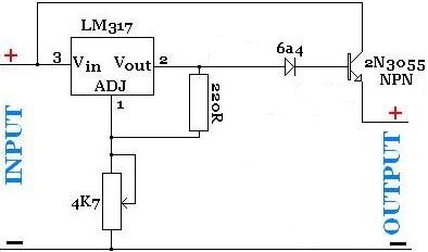
Voltage Regulator as Audio Amplifier Schematic Circuit Diagram. We can adjust the output voltage by two external resistor connected through the adjustable pin of the IC. The Circuit diagram for the voltage regulator is shown in the first image.

0 Response to "Volt Regulator Lm 37 T Circuit Diagram"
Post a Comment